Voltage Controlled Audio Slew Rate Limiter
The reason I've put this circuit here is as part of my quest for a circuit that
will come close to emulating that so called "Warm Valve  Sound". Without  using
the valves of course. Part of what I've heard in the valve sound  has seemed  a
lot like Slew rate limiting. It sounds like a low pass filter but isn't  quite.
It sort of modifies the top end a little but not actually cuts it. Why would  I
want to emulate that valve sound anyway? Why not use valves? Well you can't fit
32 12AX7s in a 1Unit 19 inch rack enclosure.

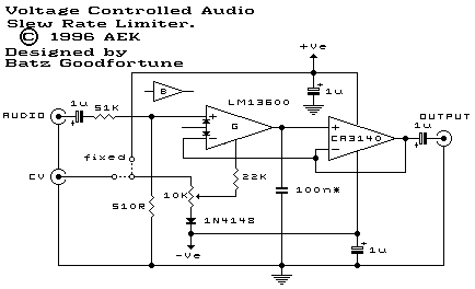
This circuit building block was based on the design  published in  the ETI  Lab
Notes volume one book. On page 35. It has been adapted to accommodate an  audio
signal and the CA3080 transconductance op amp has been replaced  with one  half
of an LM13600. This OTA is a little less noisy than the earlier 3080 but on the
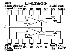
whole it is very similar. The pin-out is shown bellow.

The 13600 has the addition of a pair of linearizing diodes that can be used  to
improve  signal  handing. Since  OTAs have  a fairly  wide open  loop gain  and
usually only like very small signals. If  the linearizing  diodes are  required
some experimentation is required. The diode pins should be pulled up through  a
suitable resistor. Not used in this circuit is the output buffer. This consists
of  a  darlington pair  which is  usually used  as the  high impedance  buffer.
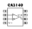
However in this case a CA3040 FET input op-amp is  used. It  is important  that
the capacitor isn't  loaded down.  The pin-out  diagram bellow  for the  CA3140
isn't exact. I don't have an exact reference for the part at this time. However
it is a  standard 8  pin single  op-amp package.  There are  probably pins  for
offset adjustment etc but I don't know what they are.

The circuit is somewhere between a low pass filter and an integrator. A  signal
at the output of the LM13600 will try  to move  towards the  input voltage  but
it's speed is limited by C1. Thus the output produces a linear ramp which stops
when it achieves the input voltage.  The slew  rate is  given by.  Slew rate  =
Iabc/C1 as volts per second.

Since Iabc is variable, so to is the slew rate. You can either hook Iabc to the
positive supply rail or you can apply an external control  voltage. This  could
give rise to all sorts of modulation possibilities. More on that later.


