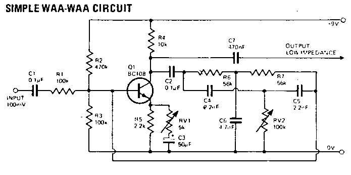
When adjusting the unit initially, RV1 is turned to its minimum value. RV2 is now adjusted and fro till a point is found at which an audible whistle ippears indicating oscillation. RV1 is then adjusted till the oscillation just disappears. RV2 is turned over its whole range and if at any point oscillation occurs RV1 is again advanced till it ceases.
It should be possible to set RV2 to any value over it's range of adjustment without any oscillation being apparent; this should also be achieved with the minimum possible value of RV1. The unit is now ready for operation.
Negative feedback is obtained by feeding part of the signal back to the base via C2. The waa-waa effect is achieved as
The values of C4, C5, C6 are chosen so as to emphasise waa-waa effect on the higher audio frequencies. This gives the sound its brilliance.